

Hi. Andy Field here & I’ll be your idiot for today.
I promised a while ago that I’d write something for the website. Seems plenty of people visit but not many actually contribute. Shame on you all! Trouble is I’m not really an authority on anything. We’ve all been riding bikes long enough to have a fair idea of what makes them go, stop & point in roughly the right direction. I’m sure you’ll agree I was never the best mechanic in the Club, or the best rider, the fastest, the brightest, the wittiest, best looking. -whatever. So what knowledge can I impart that you don’t already know? Well, take a quick scroll through the Gallery & it seems my specialist subject is Trikes. I’ve been riding 3 wheelers on & off for about 10 years now. Built 4 of my own & had a hand in half a dozen more. Got a shelf full of trophies in my garage, on half a dozen websites & had 3 creations featured in national bike magazines. -God that sounds big-headed doesn’t it! Not meant to be. I just like the artistic/creative side of building bikes & get a kick out of riding something I’ve literally built with my own hands from the ground up.
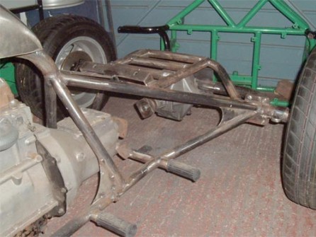
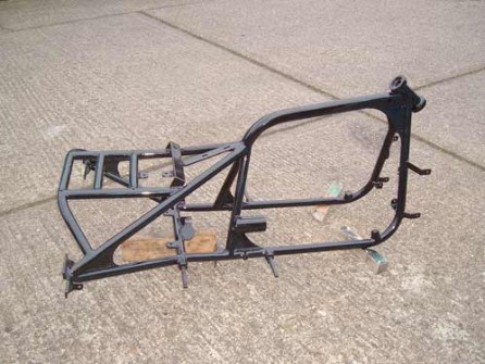
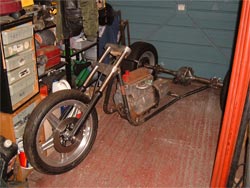
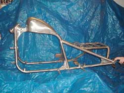
I’ve just pulled my own green Reliant Rialto engined beastie to bits & sold the frame to a friend. Been cruising around on it for nearly 4 years & just fancied a change. Nothing drastic, just simpler & tidier, re-using as many original parts as I can. At the same time as rebuilding my own & helping the new owner resurrect the old one, I’m also putting together 2 more. Number 1 is Darren’s VERY orange thing, seen regularly in the Gallery. This is the basic frame layout we’re using on all of them. A very simple “hardtail” or “rigid” setup. No rear suspension! Not as mad as it sounds -honest! Most trike riders run their rear tyres at only 10 to 15 PSI. Mine are 15. The lack of weight on small trikes means they become very skittery if the tyres are any harder & can lead to bump-steer, where hitting a bump with the back wheel throws the front end to one side. Softer tyres obviously also mean a softer ride. Most modern roads aren’t actually THAT bad & riding a hardtail is more a series of gentle bumps than spine shattering crunches. It’s just a different style of riding. More basic but also a lot more fun!
O.K, intro over. Time to build something.
 I haven’t even started on my own new frame yet, so I’ll take the next one along the production line as an example. My mate Simon is also a Postie, although at a different Sorting Office to Darren & myself. He’s been riding sports bikes for the last few years & reached the point where he wants to slow down before he kills himself! Always had an interest in custom bikes but never built anything himself. His wife, Claire, doesn’t have a bike licence but fancies riding the finished machine -trikes can be ridden on either a car or bike licence, so small, lightweight & minimalist is the way to go.
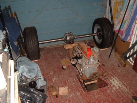
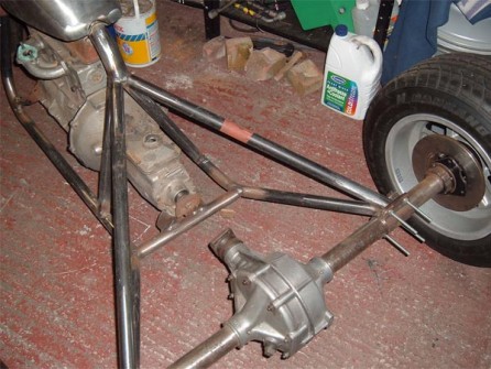
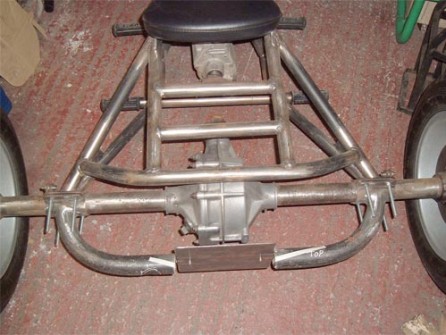
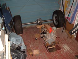
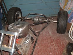
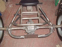
I had a few Reliant spares in my garage so we started with a Robin axle. To this we added a pair of 14” 5 spoke “Revolution” wheels that had previously graced a Ford Capri. I’d already refurbished them, having the oxidisation shot-blasted off, then powder-coating them in metallic silver, before spray-painting the spokes gloss black. 205, 60 profile tyres give an overall diameter of something like 23”. Being intended for a Ford they had a 4 x 4 ¼ PCD. 4 bolt holes spaced 4 ¼” apart measured diagonally across the bolt centres. Reliant axles use 4 x 4” so I had Doug, my local friendly engineering chappie, machine up some adaptors. These are steel rings, 1” thick, that have Reliant pattern studs sticking out of the front, & Ford pattern bolt holes at the back.
With the wheels & tyres on the axle, this then gives the height of the diff’ housing, (the differential gears in the centre of the axle), from the ground. To that bolts the prop’ shaft, which runs parallel to the ground & connects to the gearbox, which bolts to the engine. So the height of the rear tyres determines the height of the engine in the finished frame. Easy. On Simon’s he should end up with about 5” of ground clearance under his sump. I’ve got a dummy engine & gearbox, put together from empty casings, which is a lot easier to lug about & move into position than a “full” motor. So a happy few hours are spent propping all the components up on bits of wood, old paint cans & anything else that comes to hand, working out the basic dimensions of the thing. How far back from the headstock will the tank come? How much room do you need for the seat? What about the pillion? Where should the footpegs go?
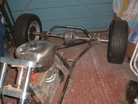
 We’re using a front end built from all my old spares, which means Ducati 900SS forks & a Honda Superdream wheel, held in 1 ½” thick aluminium yokes, with a one-off stainless wheel spindle, again machined by Doug for the extortionate fee of 60 quid the lot.
The stainless steering stem is turned to fit Kawasaki GPZ 600 bearings, simply because that’s what Darren’s front end is & we had the bearings to hand at the time! Setting the rake & trail of the forks took all of 5 minutes -prop ‘em in place & see what looks right! As a general rule of thumb, if it looks O.K, it usually is. The yokes have to be far enough forward to clear the tank on full lock & high enough to allow the top tube that runs beneath the tank to meet the headstock. These machines are deliberately low tech. A few basic measurements to ensure everything runs true & square & the rest is down to a keen eye & sense of proportion, coupled with a few year’s experience of what will work in practice. I usually spend an afternoon or so, just moving things about, trying different ideas until it looks right.
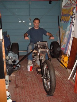
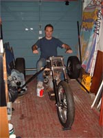
O.K, that’s more than enough for now I think. With luck there’s a piccie here somewhere of Simon riding his air trike. Next time we’ll start bending some tubing around the assembled bits & pieces so don’t knock anything over on your way out. If more of you contributed to this site, you wouldn’t have to wade through this stuff you know. It’s your own fault!
TRIKE FRAMES-BITS AND PIECES. PART 2.
 Hi. About time I scribbled down the second part of this series, but it’s a few weeks since the relevant parts were made so you’ll have to bear with me.
So where did we get to? Oh yeah. We’d gathered together the major components -engine & gearbox, axle & wheels, front end etc. & mapped out the basic dimensions of our tricycle on the garage floor. So far so good. Got a stack of tubing & a hydraulic pipe bender. What more could we need? Well how about a headstock, axle clamps, some engine mounts maybe. All those bits ‘n’ pieces that join it all together. Where we gonna get them then? Gotta make ‘em. No one sells ready-made frame parts to the general public so we’ve got to make our own. Fortunately we have the technology -a 150 MIG welder & a hacksaw.
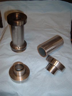
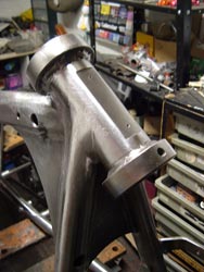
First, the headstock. We’re using taper roller bearings designed for a Kawasaki 600 GPZ, simply because that’s the front end we used on the previous frame & we’d had a couple of extra sets of bearing cups machined up. All the trikes we’re building at the moment have one-off aluminium “slab” yokes , made locally by Doug the very nice engineer. 60 quid a pair-what a bargain! He also produced stainless steel steering stems to accept the Kwacka bearings. The bearing cups are mild
steel so we can weld them & are recessed to take the outer shell of the taper rollers. They’re about 3” in diameter & have a step on the underside that fits snugly inside a 1 ½” bore mild steel tube.
We use plain, mild steel welded seam heavy gauge steam pipe for our frames -because it’s very cheap, (about a quid a foot), &, with a wall thickness of 1/8”, once it’s welded into a sensibly triangulated frame it’s as strong as a very, very strong thing. It may not be chrome moly or Reynolds but it’s wrapped around a 40bhp Reliant engine, not an R1. Take a look at the spindly little frame on your own bike & compare it to ours & you’ll see we’re 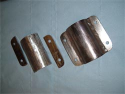 more than strong enough to be safe.
A quick dollop of weld, making sure we’ve got plenty of penetration, (!), for a nice strong joint & hey presto. One headstock.
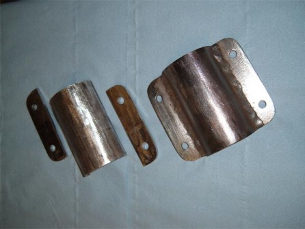
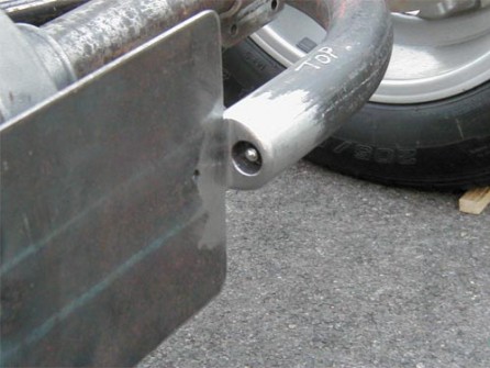
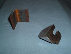
Next up is the axle clamps at the other end of the frame. These are easy. The Reliant axle we’re using has drive-shaft tubes of 2” diameter. The pipe we use is measured by it’s internal bore size, so a 2” pipe will slide perfectly over the axle. A 4” long section was cut, sliced down it’s length to give 2 semi circular halves, then flanges made from 1/8” thick steel plate. Out with the welder again. Glue it all together. 2 pieces that will clamp around the axle & bolt together. An hour or two’s work gives us a matching pair, one for each side of the axle. Simple as that. Later, these have small locating tabs added that match ones welded direct to the axle & stop the whole thing turning in the clamps or sliding sideways.
O.K, engine mounts would be nice. The main frame is built from 1” bore tube, (1 3/8” outside diameter). The Reliant engine has two front mounts that normally bolt flat onto the Reliant chassis.
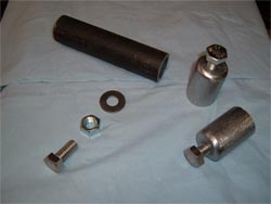 So we make up a couple of mounting “turrets” with internal captive nuts. These consist of an inch or so of the 1” frame tubing , a large washer & a mild steel 12mm nut. Weld the nut to the washer, turn it upside down & weld the washer into the end of the tube. Let it cool down & check the threads of the nut haven’t distorted in the heat of the welding by carefully screwing a 12mm bolt in. Fine. Clean the welds up & make it all look pretty with a big flat hand file & they’re done. Later the bottom end of each mount will be scalloped to fit over the frame tubing. I’ve ridden my two Reliant trikes with no rubber mounts of any kind with no noticeable engine vibration so the engine bolts directly to these “turrets” once they’re welded to the frame.
Lastly for today, we need some gearbox mounts. Reliants have two bolts on the underside of the gearbox, exiting at roughly 45 degrees. A couple of pieces of 2” wide, 1/8” thick angle iron are used. Slotted for easy fitment of the bolts, these simply sit over a frame cross member & are welded in place.
So that’s about it for today. Not a bad few hour’s work so time for a cup of tea & a cake I think.
 Maybe the text here is a bit confusing but hopefully the photos are self explanatory. Check out the Forum Gallery for a sneak preview of the frame we’re building, (Simon’s trike), showing all today’s parts in place. Assuming we haven’t inadvertently set fire to the garage with the welder, I’ll see you back here next time to start getting creative with the pipe bender. Your turn to supply the cake.
TRIKE FRAMES-THE BENDY BITS. PART 3.
O.K, we’re back in the on-line Manky Monkey Motors Tricycle Emporium.
Haven’t been here for several weeks & a few people have been asking me questions, so I guess it’s about time we started bending some tubes. Well there’s the pipe bender, there’s a stack of tubing -away you go. What? You don’t know where to start? You think I Know what I’m doing? I’m a Postman remember, not an engineer. Alright, I’ll try & show you how this particular frame was put together, but I’m sure other people would use alternative methods & come up with different ideas. That’s the beauty of custom building though. Every machine is individual & is an expression of the tastes & talents of the builder. Not sure how much of either commodity I possess, but, personally, I like very minimal, low-tech designs. Simple & functional, that’s me!
Right, let’s see. Where did we get to? Oh yeah, we’ve laid the various components out on the garage floor & moved ‘em around, sitting them on blocks of wood, paint tins etc to achieve the desired height. Once we’re happy that everything looks right -the proportions are O.K, there’s enough room to fit everything in within our imaginary frame, including the rider & pillion, plenty of ground clearance etc, we can take a few basic measurements & get it all square & symmetrical. Won’t bore you too much with that, except to say it really is worth spending time to get it right. A few hours endlessly re-checking everything with a tape measure, steel rule,  spirit level & square is definitely worth it in the long run. At the end of the day, as long as the headstock is level, (we use a simple plumb-bob to ensure it sits right), & the rear axle is at 90 degrees to it, the finished trike should run true, without crabbing off to one side & ending up in the gutter. We measure from a central point on the engine, (on Reliants there’s a casting seam that runs up the middle of the gear-box bell-housing. Cant use the cylinder head or rocker cover as they’re off-set to one side), to the centre of the axle diff housing. From the ends of the axle tubes to the centre line of the engine. We line up the centre-line of the headstock with the centre line of the motor, using the crankshaft pulley bolt as a reference, then measure from there back to both sides of the axle etc, etc. Everything is measured, shuffled about, measured again, checked with the measurements from the opposite side of the frame -well, you get the idea. We work directly off the concrete garage floor as we’ve already satisfied ourselves it’s as level as any work bench we could knock up. Reference marks are drawn in case anything gets accidentally moved.
So, pass me a length of that tubing will you. The 1” bore stuff leant against the wall over there.
This comes in 20 foot lengths -or whatever the metric equivalent of that is, but our local supplier chops it in half
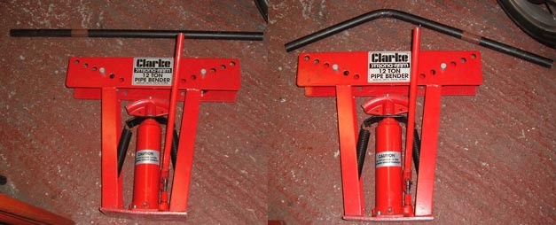
on request to make it easier to get home. At roughly a quid a foot, it’s not the end of the World if we make a mistake so don’t be afraid to get stuck in. First off, we need to support the headstock, We’ve decided it looks best 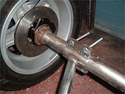 at roughly 45 degrees. That will give us plenty of straight line stability without making the steering so heavy we can’t manoeuvre it at slow speeds. The front down tubes are vertical as we intend to hang the radiator on these so we need to put matching 90 degree bends in two lengths of tube. If you’ve never seen a hydraulic pipe bender before, there should be a photo hereabouts.
It’s a very simple machine. We bought ours new for about 85 quid. A glorified hydraulic bottle jack with a curved former on the end, sitting in a framework that supports a pair of rollers. The forming heads are interchangeable for different sizes of tube & the rollers can be moved to vary the tightness of the bend. Simply lay the tube into the former, pump up the handle & as the tube is pushed against the rollers it creates a bend. The trick is in making matched pairs of bends. For this we use an angle-form. Two flat metal straps held together at one end with a nut & bolt which can be set at the desired angle then checked against the tube as you bend it. The tube tends to spring back slightly as it’s released from the bender so we allow for that with an extra couple of pumps on the handle. A little practice on a spare piece of tube & you’ll soon get the hang of it.
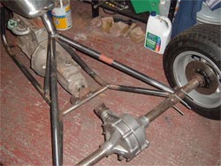
So we’ve measured from the headstock down to the engine mount, allowed a couple of inches extra, & bent the tube. A little of the length is lost in creating the bend but this varies depending on the diameter of tube used & the tightness of the bend. Always better to cut a tube too long than bend it & find it’s half an inch too short. On our frame the centre-line of the down tubes sits 4” in front of the engine mounts to give room for the electric radiator fan we’ll be using. We know the height of the headstock from the ground, so we can lay the two bent tubes along under the motor, blocking them up off the floor to the right height & set them at the right width to line up with the engine mounts. The vertical down tubes can then be angled inwards to meet the headstock. A little work with an angle grinder & a file & the ends are scalloped to fit neatly around the headstock tube. This is one of the most important joints on the whole frame so we’re very careful to ensure the down tubes are symmetrical & that the headstock sits square & along the centre-line of the engine. Difficult to explain.
 Meanwhile, at the back end, we’ve bolted the axle clamps we made last time around the axle an equal distance in from the hubs & checked the mating face between the two halves of the clamps sits vertically. Now we need to put a second bend in each frame tube to bring them up to meet the clamps. In our case the tube needs to kick out by about 6” & up by around 4 or 5”. No easy way to explain this either, but it took us several hours of gentle bending, trying in place, head scratching, bending a little more & so on, to get it right. Even then we had to heat the second tube with a blow lamp & tweak it slightly to get it to perfectly match the first.
Once that was done, the ends of the tubes were scalloped to fit against the back of the clamps then tack-welded in place, (a small, temporary weld just to hold them in position).
With the engine mounts we made earlier bolted to the motor & sitting on the frame tubes the headstock is laid back in place, measured, double-checked, tack-welded & checked again.
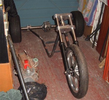
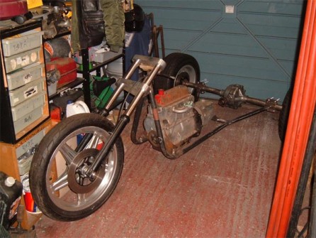
So now we can carefully slide the front end into the headstock & we’ve got all three wheels tied together, giving us a rigid base from which to start building our frame.
This has all got a bit complicated & wordy but hopefully the photos explain it a little more. We use very basic methods but take plenty of time to ensure the results are as accurate as possible. Three of us have checked every frame dimension in every direction & can honestly say it’s spot on. I’d be happy for anyone to run a spirit level & tape measure over it. And the frame.
Alright, next time we’ll sort out the gear-box mounts & start building upwards from our bottom rails. I’m hungry after all that. Anyone remember to bring some cake?
TRIKE FRAMES-ONWARDS & UPWARDS. PART 4.
Hi. Come on in. Glad you came back. I’d feel stupid just typing this to myself.
 Right-o then, let’s get cracking.
Last time you were here we’d set all the running gear for our trike out on the garage floor, propped the complete front end up in place to determine the height of the headstock from the ground & the angle of the forks, then we bent a pair of tubes to form the down tubes, running back under the engine to meet the back axle. So we’ve got the bottom cradle of our frame tack-welded together. The engine is sat on it’s front mounts, which we made several chapters ago, (hope you were paying attention). Now we need to support the back end of the motor. That’s easy. Check the engine is sitting level with the ground & square within the frame. Take the two gearbox mounts we’ve already made & bolt them to the underside of the ‘box. Cut a length of 1” tube to fit across the frame rails, scalloping the ends to fit snugly over them. Offer it up to the mounts & weld together where they touch. Weld the ends of the tube to the frame on either side, checking with a square that it’s…square, & if all’s well, when you take away whatever you’ve blocked the engine u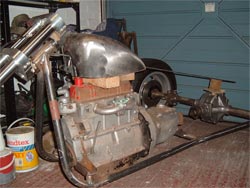 p off the floor with, it should remain suspended in the frame. If it falls to the ground with a clunk, go back a few lines & do the welding bit again. Maybe you forgot to switch the thing on.
I’m assuming anybody who actually tries to put this rather sketchy information into practice already knows how to weld, so I won’t bother with advice on correct penetration, (!), wire thickness etc. We use a 150 MIG welder with 0.8 wire & Argonshield gas though.
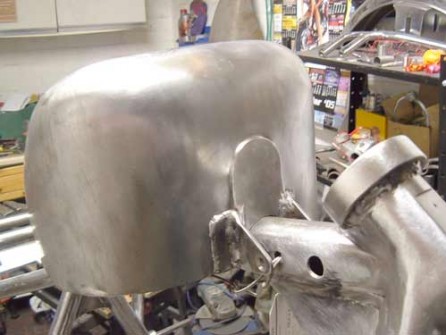
Alright, what’s next? Top tube? Again, not as difficult as you might think. None of this is really. It’s just a matter of having the confidence to get stuck in. If you mess it up, cut another piece of tube & try again. Because we want the finished trike to look small & lightweight, we’ve opted for a King Sportster petrol tank. This is an off the shelf aftermarket custom tank, loosely based on the Harley Sportster one but a couple of inches wider. With it propped up on top of the motor in roughly the right position, we can check there’s 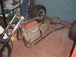 enough room for the forks to turn onto full lock, then measure up for the top frame tube. For this we use 1 ½” bore pipe. The tunnel under the tank is just under 2” wide, so we’ve had to shave the sides of our tube a little with Mr Angle Grinder.
In the photo you can see we’ve used an old length of flat bar to show the line the top tube will take under the tank. This lets us check we’ll have enough room to get the engine in & out of the finished frame. It also gives us an idea of the angle needed to bring the back end of the tube down behind the engine & how long the tube has to be to accommodate the
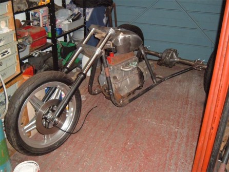
tank. Out with the angle form we made earlier, set it to the required angle, bend the tube to suit & trim it to length. All’s well so we can offer the tube up, scallop the front end around the headstock,then glue it in place with the welder. Easy! A line is taken from the headstock to the centre of the axle diff’ housing to check everything’s square & centra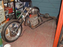 l. Lookin’ good. Next we need to support the end of that top tube. Back to the 1” pipe again. Two lengths are cut to fit between the end of the top tube & the bottom rails. They’re angled back a little as this will brace the front of the frame better than a vertical tube. The angle is purely personal choice but obviously needs to clear the gearbox casing. In addition, we plan to make up a new gearstick that will come out sideways from under the seat so these tubes have to be placed to allow room for that as well -and you thought we just made this up as we went along! A bit of head-scratching, standing back & squinting at it, trying scrap bits of pipe at various angles & drinking tea, then the tubes are cut, scalloped to sit on the bottom rails, notched at the top to fit under the top tube, & welded in place. Hey! Now we’ve got a completed engine cradle! Are we good or what. Have another cup of tea.
 Lastly for today, we need to tie the front cradle to the axle. More 1” tube. We chose to run it from the point where the previous tubes meet the top one, straight back to the axle
clamps. This just happens to give us enough room beneath the seat for our proposed gearstick set-up & more importantly, looks good!
O.K, that’s about it for today. We’ve built the basic structure &, personally, I think it’s not looking bad at all. Next time we’ll run a tube across the back end to tie the two axle clamps together & have a look at the seat frame & footpegs. These ramblings aren’t really intended as a step by step guide to frame building though. As I’ve already said, everyone has their own ideas of how it should be done, but hopefully it’ll show what can be achieved with basic tools & facilities, (Nigel, your garage isn’t a glorified cupboard really, it’s very nice -honest!), & a bit of common sense.
Ya all come back now, y’ hear.
TRIKE FRAMES-SEATS ‘N’ STUFF. PART 5.
 Good morning class. Are we all here? Right. Open your books to chapter 5 -& pay attention at the back -I’ll be asking questions later.
Everybody sitting comfortably? Then we’ll begin.
In the opening paragraph we find our impossibly handsome & erudite young hero deep in the vast caverns of the Manky Monkey garage, surveying the skeletal steel sculpture that has haunted his dreams these past few Trike Frameweeks. A frown creased his perfectly honed brow. Something was missing. “I need somewhere to perch me arse” he mused.
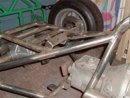
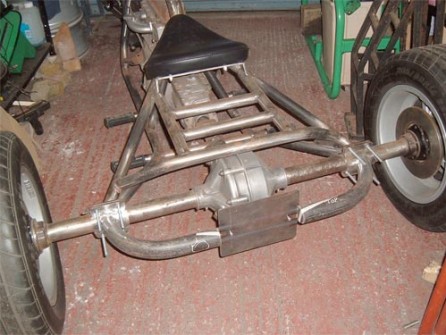
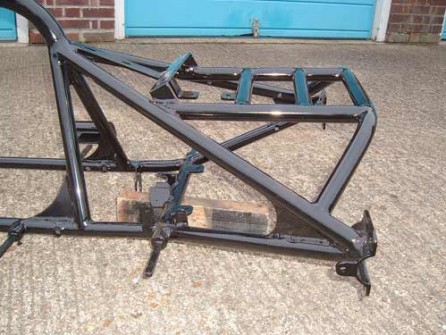
O.K, now we’ve knocked up the basic outline of our trike frame, it’s time to start adding some of the secondary tube-work. First up is the seat frame & luggage rack. We’re using a 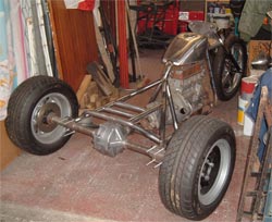 large universal fitting solo seat, bought for 40 quid from the Netley Marsh auto jumble last year, coupled with a home-made removable pillion pad that’ll clip onto the luggage rack. The rack is an integral part of the frame &, following the Manky ethos, is minimal & dual purpose. As well as providing luggage & pillion carrying space, it also ties the two axle clamps together to stop them spreading & braces the rear of the frame from front to back. We used a length of our 1” tube, with a 45 degree bend at either end, to bridge Trike Frameacross from one axle clamp to the other, rising up over the diff housing & welded to the frame just ahead of the clamps. From this we then ran a pair of tubes forward, parallel to the ground, to meet the nose of the “hardtail”, (the name given to an unsprung frame by we custom bike dudes). With a little careful measuring, & a lot of luck, these tubes are the same width as the rider’s saddle so tuck neatly under the back of it. The rear loop also has to be just the right height to achieve this while keeping the rack horizontal.
 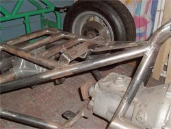 Have a look at the photos to see what I mean. A couple of short tubes were then cut, scalloped & tapped into place to form a platform. A quick check with the engineer’s square & everything was tack welded together. We now have a luggage rack/pillion seat mount that also substantially braces the rear of the frame.
Trike FrameWhen we originally set out our frame dimensions we didn’t just bung the axle clamps on any old where & hope for the best. No, we’re much cleverer than we look. When the rider’s pad is fitted it’s edges follow the line of the hardtail down to the clamps. Smooth, uncluttered, flowing lines. See, told you those few hours spent moving  components around on the garage floor would be worth it. The saddle has four mounting studs on it’s underside, so some off-cuts of 2” wide flat steel strap were fashioned into a seat support & fitted to the frame.
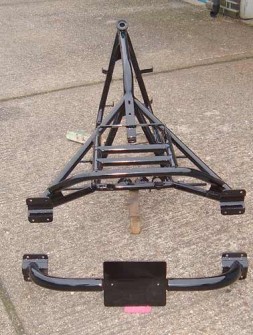
I’ve been keen to try out an idea for a number plate mount for a while now, so we’ve used it here, just to be a little different from Darren’s orange trike. I took a length of the 1 ½” bore material we used for the top tube, added a 90 degree bend at either end & created a “bumper” Trike Frametube around the back of the axle. This is welded to the rear half of the axle clamps so they now bolt to the frame as a one-piece unit, further bracing the hardtail. A section was then cut out of the centre of the bumper & a 3mm thick steel number plate mount was welded in place. This has captive M6 nuts welded behind it to screw the plate to. Notice the two parallel lines of perfect weld penetration on the face of the plate -damn I’m good!
Several number plate lights were tried before the final solution was found. Quite chuffed with these actually. At the moment, all the shaven headed, baseball hatted numbskulls are 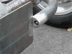 adorning their clapped out hatch-backs with little blue LED lights. These are basically a hollow M6 bolt with a small but very bright LED mounted in the head so they can Trike Framebe fitted into a hole drilled in the car’s bodywork & held with a nut from the back. After a little shopping around I managed to find a pair of white ones. I welded an M6 nut to a washer then into the end of an offcut of 1” Tube. These were then welded in place on either side of the number plate giving recessed housings that the LEDs screw directly into. The wires travel inside the bumper & exit through holes near the axle clamps. A very neat & subtle set-up that only cost 7 quid for the lights & a bit of time with the welder, hand file & bits of scrap tube. Just wait -everyone will be nicking that idea next year!
Lastly for today, we need some footpegs. The rubbers were bought from a spares catalogue & are pattern BSA items. They mount on a square bar roughly ½” thick, but to achieve this we had to weld two flat Trike Framepieces together ‘cos that’s all we had knocking about in the garage at the time. After much experimenting with our trusty old paint tins to find the optimum comfy riding position for Simon’s little legs, ½” holes were drilled in the frame rails & the square bars welded in place. Hmm, I guess they must be the square pegs in round holes you hear about. To space the rubbers out from the frame to the desired width, sleeves of 1” tube were cut & slid over the pegs, welded to them & to the frame. Hopefully that’ll give a nice solid finished footpeg. The pillion pegs were made in exactly the same way & positioned to line up with the gearbox cross member, simply because they looked right there.
 So that’s about it for another week. All the tubing is now done. A quick measure up shows we’ve used about 32 feet of 1” bore grade 3 ERW Trike Frame& 6 or 7 feet of 1 ½” bore. Add the cost of the gas & wire for the MIG welder & the basic frame has come to around 100 quid so far. Plus my welding, fabricating, tutorial & journalistic fees of course! Don’t suppose any of you lot brought a cake for the teacher? No, thought not. Very partial to jammy doughnuts you know. And it IS my Birthday next week. Oh well.
Next time we’ll run through the various mounting tabs & add a few strengthening gussets. I hope these lessons show that even the most complicated looking designs are just a matter of lots of forward planning, a bit of imagination & taking it one small step at a time.
Class dismissed.
TRIKE FRAMES-TABS & TRIANGLES. PART 6.
 Well, here we are then. 2nd to last chapter. I can’t think of anything more to add so let’s close the series with a quick run through the various mounting tabs & strengthening gussets & then I’ll unveil the finished frame. Hey! No cheating & scrolling straight to the bottom! Get back up here! This is for YOUR benefit. I already know all this stuff. I COULD be in the pub you know, or out on me bike, or eating cake with me feet up in front of the telly. Least you can do is read it. That’s better. Now, where was I? O.K, they reckon a photo saves a thousand words & I’ve got
  a dozen of ’em to use up, so with luck I’ll never have to write anything ever again. -I heard that! Just wait till Karen threatens YOU with a rolled up copy of MCN & forces you to type till your fingers bleed. Right. Pay attention then. Here we go.
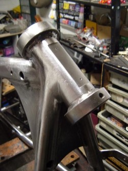
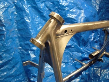
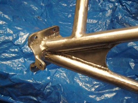
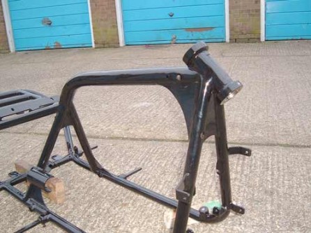
Here we have the finished headstock. Pretty ain’t it! We were originally going to leave all the frame welds in their natural state but in a moment of madness decided to grind & file them smooth. Never, ever again! Simon spent days Trike Frameworking on this bit with a selection of hand files. Trouble is once you start cleaning the welds up you have to do the whole frame or it looks silly. MIG weld is particularly hard & 3 of us have spent several weeks of afternoons & evenings hunched over this damn frame filing, building up the low spots with more weld, & filing again, being careful not to cut too far in & weakening the joint. Because this frame’s being powder coated we couldn’t use any filler ‘cos it won’t survive the heat of the drying oven, so everything you see is solid metal. We decided we could get away with leaving the straight lines of weld untouched so 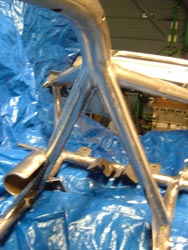 just cleaned back the joints between tubes.
The headstock needs some serious bracing. Not being able to lean a trike like you can a normal bike, this area is subjected to some very Trike Framestrong turning stresses. Better to over 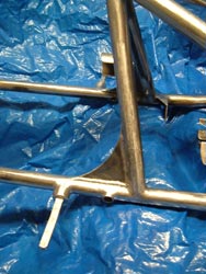 engineer than skimp on materials & wish you hadn’t as you’re heading for the ditch. We’ve used 1/8” steel plate to form a strengthening gusset on each side of the frame with another between the front down tubes. Each one is 4” by 4” . Just to make it look pretty we’ve radiused the exposed edge of the triangles to give the frame a less angular look, & set the gussets along the centre line of the tubes to show off their lines.
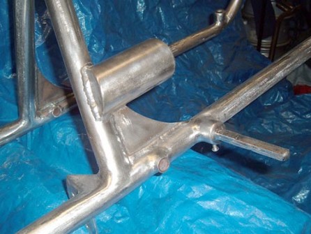
This photo’s a bit fuzzy, but it’s the only one I’ve got that shows the small triangular gusset beneath the nose of the seat. This obviously helps to brace the junction of several tubes, spreading the load between the two uprights, & also disguises the sharp angle at the top of these two tubes. On the next frame these uprights will be placed vertically with a bend inwards at the top to meet the top tube. On the left you can see the shroud we added to cover the exposed pinnion gear of the starter motor. Nothing more embarrassing than hitting the ignition & winding your trouser leg into the starter. This is simply a section of 2” diameter tube that sits over the cog with about ½“ of clearance & is welded to the upright Trike Framewhere it touches.
At the base of the uprights we’ve added more 1/8” thick triangular gussets. These brace them where they lean forward & help to support the top tube. They mirror the radiused headstock giving the engine cradle a more complete, rounded look.
 I’ve got a mate with a small lathe in his shed who’s knocked up all sorts of spacers & bits & bobs for these trikes. Hello Reg! Among them are the pivot points for the pedals. These are tubes welded across the bottom frame rails, bored to ½” diameter, with each end machined to take a phosphur bronze bush for the pedals to turn in. A pack of 5 bushes was a quid at last year’s Beaulieu auto jumble. The gussets deliberately extend over these pivots to brace the bottom rails where they’ve been bored. YOU bored yet? No? O.K, next.
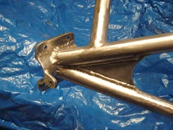
The opposite side of the frame, showing the starter motor pinnion shroud. Below the footpeg you can see an M6 bolt. We drilled & tapped the underside of each Trike Framepeg to take a bolt that will act as a stop for the pedals, preventing them from clanging against our nice shiny coated frame. With a bolt & lock nut we’ll have some adjustment on the pedal height. Behind the upright you can just see the mounting bracket for the Girling brake master cylinder. All three brakes will be linked together on one pedal, removing the need for a lever on the handlebars. The braided stainless brake hoses will run inside the bottom frame rails, while the bulk of the wiring loom will be routed through the top tube.
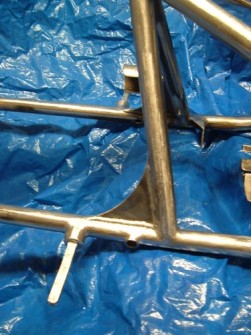
The last gussets are at the pointy end of the hardtail. These obviously add some strength to the first point of contact for the vibrations caused by running without rear suspension, 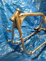 & also look kinda nice I think! Nice big welds around those axle clamps. Notice the small locating tabs on Trike Framethe clamps. These bolt to corresponding tabs on the axle itself to stop it from turning in the clamp or sliding sideways. Go on, admit it, we’re cleverer than you thought we were!
Alright. That’s all the strengthening gussets covered. Back to the front again -?
Here’s a fuller picture of the engine cradle. In the bottom bearing cup of the headstock we’ve drilled & tapped an M8 thread to take the shiny stainless steel steering stop that Reg made for us. This is basically a sleeve around an M8 allen bolt & corresponds to two more fitted to the bottom yoke. Being stainless they don’t need painting so won’t get chipped when the forks are dropped onto full lock. We’ve allowed roughly 45 degrees of turn in each direction. Of course, with the Reliant Trike Frameengine we’ve also got reverse gear, which makes 3 point turns a 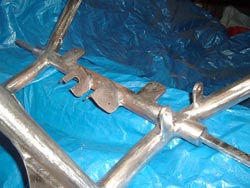 whole lot easier. You can also see the VIN plate mount on the headstock, a wiring loom hole & tank mount in the top tube, a brake hose hole in the down tube, mounts for the Mini radiator ahead of the down tubes & tabs for the Suzuki Intruder electric radiator fan between them. Further down are the front engine mounts & beyond that the starter motor shroud again. All make sense? Good.
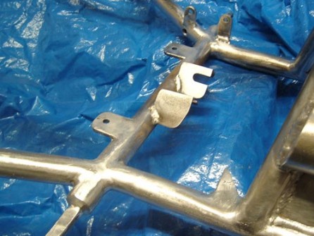
These are the gearbox mounts. Like the front turrets, we don’t bother with rubber mounts here. Don’t seem to need ’em. In the foreground are the tabs for the Metro handbrake lever. Regulations state this must be situated so as to be accessible by the rider while seated. Makes sense really but I’ve seen plenty of trikes with levers tucked away on the back axle. We use modified VW Golf cables to hook up to the rear calipers. The  handbrake must also be a “separate mechanical system”, which counts out the hydraulic line-locks I’ve seen on some machines, & must operate on all the wheels on any axle. That means a pin that locks the front brake lever in place would do, although technically that would be Trike Frameoperating the existing hydraulic braking circuit I suppose. The Golf/Passat calipers we use have a dual operated piston.mount. It sits on a screw thread & under normal braking the whole assembly is moved by hydraulic fluid, then when the handbrake’s used the piston is mechanically screwed out to lock on the brakes. Nice & tidy.
The large tabs behind the gearbox cross member are the lower mounts for the battery box. Haven’t made this yet but we’ve still got the cardboard mock-up we made for Darren’s 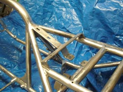 which seems to fit. The box has removable sides & is a horseshoe shape to sit over the propshaft with the battery on the right & the rest of the ‘leccy gubbins on the left. The exhaust silencer also hangs from one of these tabs, with the tail pipe hung on a couple of bolts welded to the back of the number plate.
Trike FrameSame thing. Other side.
Here you can see the seat frame & the top battery box mounts. These are made from 1/8” thick, 2” wide flat steel strap. The handbrake, radiator & fan tabs are 1” wide.
Wanna see the completed frame now?
Well sorry, but I’m going to keep you in suspense just a little longer. -Ha Harr!!
Got just enough photos left to spin it out for one last chapter, so watch this space!
TRIKE FRAMES-BACK IN BLACK. PART 7.
Part 7. Whod’ve thunk it eh? I’m sure you’ll be relieved to know this is the final, final, definitely last ever chapter of this series. Maybe.
It was supposed to be just a few quick lines on knocking together a frame, just to give you a rough idea of what’s involved, (& to fill some space on the website!). Seems to have grown & grown though. If you’ve stuck with 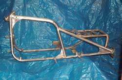 me this far I assume you’re actually interested in it all, so although this is the last piece of the frame story, I’ll bung in more build updates as & when there’s some progress to report. My job was to design the trike as a whole & create the frame. Now it’s up to Simon, the owner, to put it all together -with a little help & supervision from yours truly. Conceptual artist, design consultant, fabricator -is there no Trike Frameend to my talents. And all for free. I’m far too nice for my own good you know.
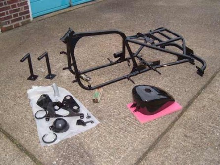
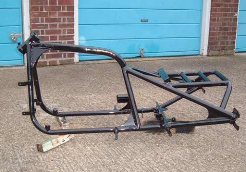
So what can I show you to bring this blockbuster to a close? Wanna see the finished frame, fresh from the coaters, in glorious, glossy black? O.K then.
This is how we last saw it. It’s taken several months of odd afternoons & evenings to get to this stage. We’re not particularly fast workers & everybody has jobs, social lives, 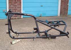 partners & all sorts of other stuff that get in the way & slow things up. If we’d worked flat out, every day, with all the materials to hand & all the machined parts ready-made, we could Trike Frameprobably produce this in a couple of weeks. But real life ain’t like that!
Ta daa!!
The moment you’ve all been waiting for! The finished Manky Monkey Motors frame.
Oooh! Don’t you just want to run your fingers over that super shiny, smooth, glossy black finish! Well don’t even think about it. We don’t want your sticky little finger prints all over it! Go on, stand over there, out of reach. For those of you who don’t know, this is powder-coating. I’ve said all this before, but at 100 microns thick, it’s 5 times thicker than normal paint & is much more weatherproof & hard wearing. It’s also petrol & brake fluid resistant. If you’ve been browsing the Gallery you’ll Trike Frameknow I use it on all my bikes these 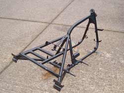 days. It’s a softer finish than paint so tends to scuff, rather than chip or flake & will accept a suprising amount of flexing without damage. I’ve used it on coil springs with no problems. It’s also about half the cost of a normal paintjob. It can only be used on metal parts though, which must be free of body filler. The components are hung in a spray booth on metal hooks & a small static electrical charge passed through them via the rail the hooks hang on, before the dry powder is sprayed on using a modified paint gun. It clings to the charged metal surface then, when put in a drying oven for an hour or so, melts & forms a smooth continuous coat. Clever huh?
Several design alterations, lots & lots of head scratching & just standing, looking at it, hours & hours of hack-sawing, bending, welding, Trike Frame& back-breaking filing have gone into this. Quite a few cake breaks too.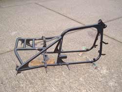
I think it was worth it though don’t you?
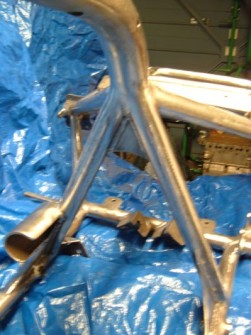
Look at the arse on that! Really pleased with the way the hardtail’s worked out. I’ve tried to keep it as simple as possible while still being structurally sound & hopefully pleasing to the eye. There are only 9 bends in the whole frame but careful planning means it manages to look nice & curvy while actually being mainly straight lines for greater strength. Radiused gussets at the main stress points help the rounded look as well. The bumper bar was a new idea that worked out surprisingly 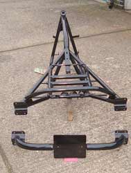 well. Originally intended as just a carrier for the number plate, it helps to visually & physically tie the back end together, adding a nice continuous curve to what would otherwise be a fairly pointy, angular part of the frame. It’s made from the same 1 ½” bore as the top tube because the smaller 1” would’ve just looked too skinny. Shows off that glossy black coating well Trike Framedoesn’t it. The number plate is a standard 9” x 7”.
Rigid frames just look so clean & uncluttered don’t they. I’ve been riding hardtails for years & happily do a hundred miles between petrol stops quite comfortably. They’re definitely an acquired taste & can be a bit lively at speed on bumpy country lanes, (can’t they Karen!), but are perfectly happy on normal A roads. You do get very good at spotting pot-holes though, but unfortunately, with 3 wheels spanning the road, you’re guaranteed to hit them with at least one corner! You can see here how the welds on the rack/pillion frame-work have been smoothed  out. Looks lovely -nice, flowing lines. SO much time & effort has gone into making this all look deceptively simple.Those gussets are an eighth of an inch thick. The down tubes are an inch & three eighths Trike Frameoutside diameter & the top tube is over an inch & three quarters. It might look small & lightweight, but this frame’s built like a Sherman tank. You can’t see them, but I’ve built two recessed LED light mounts, similar to the number plate ones, into the underside of the top tube. These LEDs are blue & will be wired into the normal lighting circuit to illuminate the polished & powder-coated engine at night. They’re matched by blue neon spark plug caps that flash as the plugs fire. Simon’s idea. In all other areas I was given a free hand to do more or less what I liked, so they’re my one concession to the customer. I may be an artist but one has to be commercial you know.
 My original design had the tank sitting level to the ground, but once the Trike Framebasic frame was built Simon decided he wanted to be sat lower “into” the trike, rather than feeling perched up on top of it. Could’ve dropped the seat height by another 2 inches but that would’ve meant ripping the back end apart again. The only other change we could make was to raise the nose of the tank by 2 inches. It now follows the line of the top tube. That meant cutting off the standard front tank mounts & making up new ones, plus welding a fill-in panel into the front of the tunnel. I later ended up replacing the rear mounts with tidier ones too. Our MIG won’t weld the thin sheet of the tank without burning through so I grafted the new mounts onto the factory welded brackets -the sticky out bits with the bolt holes in are mine. The ugly patches on the face of the tank are theirs. My tunnel filler plate is welded to the original raised welded Trike Frameseam of the tank. I didn’t want to grind it back flush & risk it leaking so decided
 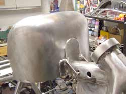 to make a feature of it instead. I also donated a flush-fitting aircraft-style filler cap from a previous project which has replaced the raised screw-on cap, so quite a lot of work has gone into this little petrol receptacle! Slap a nice thick coat of powder on it & you’d never know it didn’t leave the factory like this. If anybody dares stroll past this bike at shows & just glance at it, they’ll be dragged back & forced to admire it! Here we see the tank being demonstrated by my lovely photographic assistant, Simon.
All these parts, including the satin black headlight shell, a couple of metallic silver parts for Darren’s orange trike & the two right-angled Trike Framebars, which bolt to the floor of my garage to padlock the door to, shot blasted & coated, came to 100 quid. What a bargain! Dropped them off on a Monday afternoon. First thing Wednesday morning I got a 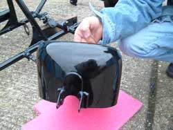 phone call to say they were ready for collection, all wrapped up in protective foam sheet. They’re an industrial coater though, rather than a show quality one, & because they shot blast & spray in the same workshop, you occasionally find little pin heads of grit trapped under the coating. There are one or two on this frame but fortunately they’re all in areas where they won’t show. For that cost we won’t complain though. The frame, yokes, tank & bars will be gloss. The lights, battery box & mudguards will be satin. The saddle will be sat on. Taken in the Manky photographic studios. The hand on the right belongs to Nigel, my Trike Framegarage elf. The whole thing has been built with just a pipe bender, a MIG welder, a 4 ½” angle grinder, a drill & a hacksaw. Oh yeah, my tip of the day: I use a white “Tippex” correction fluid pen for marking metal. Easy to see, works on any surface & can be rubbed off if you make a mistake! The only specially machined components were the
 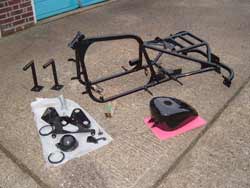 bearing cups in the headstock, the pedal pivots, 2 horizontal tubes welded into the top tube to mount the tank to & 4 vertical ones set into the corners of the rack to take the locating pins of the removable pillion pad. We had a pair of aluminium yokes machined up as well, but only because I knew a man who could at an affordable price, otherwise we’d have used standard factory ones. No special jigs or patterns. Just a plumb-bob, spirit level, engineer’s square & steel rule. And lots & lots of Trike Framemeasuring, checking & checking again! Everything was temporarily tack-welded in place & wasn’t fully seam-welded until we were absolutely sure it was right. Having said that though, we weren’t working to any sort of plan or drawing. Just ideas in my head.
 The proud owner shows off his steed. There’s something very satisfying about creating something literally from nothing. A totally one-off design, tailor-made for him. It looks tiny but Simon’s really 7 foot 6! Harr ha ha! No he’s not. He’s a little vertically challenged, bless ’im, but at least he won’t have to worry about reaching the ground now. It fits him perfectly. Hopefully he’ll get a lot of fun out of riding it & can confidently park it alongside the best of them at shows & rallies.
Trike FrameThe face behind the mask. -Wha’dya mean, put it back on! 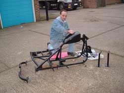
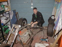
The author at work. Well, that’s about it folks. Really can’t think of anything else to tell you. We’ve covered everything from a pile of grubby parts on the garage floor, to a fully finished, custom built frame. Wasn’t too difficult was it! Nothing that can’t be achieved with a few basic metal-working skills & some common sense. Next time you’re at a bike show, take a closer look at the custom stuff -could you do better? What would you change?
Well, I think my work here is done, so I’m off to start my next Manky masterpiece. Pass me that hacksaw will you!
 This show was brought to you by the letter M & the number 3.
The cast in no particular order were:
Simon -owner of the finished frame, who paid for all the materials used, got in the way & kept us supplied with chocolate.
Nigel -Owner of the garage where the deed was done, now ankle-deep in grinding dust & metal off-cuts. New owner of my old frame.
Darren -Owner & co-builder of the previous project, who wasn’t directly involved in this build, but has been on hand to eat cakes & take the mickey whenever necessary.
Yoda, the Webmaster, who has steered me through the intricacies of this new-fangled technology & posted the results here for you -& put up with my constant proof-reading niggles.
Karen, our lovely but slightly scary editor, who cajoled me into putting digits to keyboard for your information & entertainment, (I hope).
And me! Andy. Who’s spent his afternoons & weekends toiling away in the garage, & his evenings hunched over a keyboard, trying to explain it all to you lot. Feel like I’ve cut, welded & ground enough steel in the last few months to build an oil rig.
A couple of phone numbers for those that may actually be inspired to try a little project of their own:
Reg Lock. Self employed machinist, who produced all those little bits & pieces without which this creation would never leave the garage. Basingstoke, Hants. 01256-333108.
Doug Newell. Manager of “Waldham Precision Engineering“, who made the aluminium “slab” yokes, stainless steering stem & mild steel headstock bearing cups. Basingstoke, Hants. 01256-359898.
“Pipeline”, who supplied all the tubing used. Basingstoke, Hants. 01256-868200.
“A & C Shotblasting”, who will blast & coat just about anything, quicker & cheaper than just about anybody. Newbury, Berks. 01635-523775.
O.K, that’s me done. Hope it’s been of some use to somebody out there. I’ve enjoyed putting this write-up together so I’ll add a few more short pieces as the final build progresses & throw in a couple of extra chapters on my own new frame as well.
Will the last one out of the garage turn out the lights please.